CJOB is a graphical user interface to help you layout your exposures on the wafer. Before CJOB it was necessary to use a text based scripting language to run jobs. Whilst this had some nice features it was not the easiest environment to learn (or teach!) and was prone to syntax errors. CJOB is both easy to use and extremely powerful and allows you to quickly try many different options and see the results displayed graphically. You should play with cjob and get a feel for how it works.
In this section we will look at the CJOB program structure and give examples with increasingly complex layouts.
CJOB environment
In the normal way you should open a terminal window and move into your environment and then into the jobs directory, from here you can type cjob to run the program.
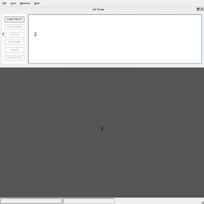
Cjob opens with 3 panels 1) building blocks 2) design 3) graphics. The basic concept behind working with CJOB is drag and drop. In order to build up the exposures on your substrate you simply drag and drop building blocks from panel 1 to panel 2, the resulting layout is shown in panel 3. Apart from the first block (SUBSTRATE) all other blocks are dropped on top of previous blocks. The technique is to pick a block up from panel 1, move it on top of another block in panel 2 until the “+” sign appears and then release the block, after this a window will open where you can fill in appropriate parameters. The minimum cjob file should consist of 1 SUBSTRATE block, 1 EXPOSURE block, 1 LAYOUT block and 1 PATTERN block. Each EXPOSURE block will increase the design horizontally, each LAYOUT block will increase the design vertically. Don’t worry about this yet, things will become clearer with the examples.
Other concepts include the following;
- information pop ups will normally appear in the graphics window when you point the mouse at an object (pattern, marker etc.) and press Ctrl, right-click on a block in panel 2 lists available actions for that block.
- Cjob does not show your actual pattern, it shows a rectangle that is the size of the pattern you’ve selected. However if you right click on the PATTERN block in panel 2 it gives you an option to run CVIEW.
- Different patterns are shown in different colors both in the design panel and the graphics window.
- Red boxes are CJOBS way of telling you that something is wrong, green boxes mean you’re good to go, very often you won’t be able to click OK and exit a particular page without filling all necessary options.
Exporting Jobs
Your exposures are not run from within cjob. Once you have completed all the exposures you want to write on your wafer you need to export your job from cjob. This is very easy. Firstly make sure you have saved your job (you will be promoted if you haven’t).
Go to File>Export. Under the Exposure column click on the name of your exposure, notice the correct layout appears in the graphics panel. In the File name box your job has automatically been given the name of your substrate followed by the exposure you selected. You can change the name if you want. Now press Export to export this job. Try selecting and exporting other jobs, if you have more exposures than one. When you’ve finished exporting all the exposures you want to write on the wafer press Done.
This is all best illustrated by diving straight into some examples. If you are new to cjob you should look at the examples in the order given below. In these examples there will be many options and windows that will be ignored, this is done deliberately for clarity. There are 5 examples each example is slightly more complex than the previous one or introduces a new option. Later examples are built up from the simplest first ones.
CJOB example 1 – single exposure
Below is an example of a simple layout.
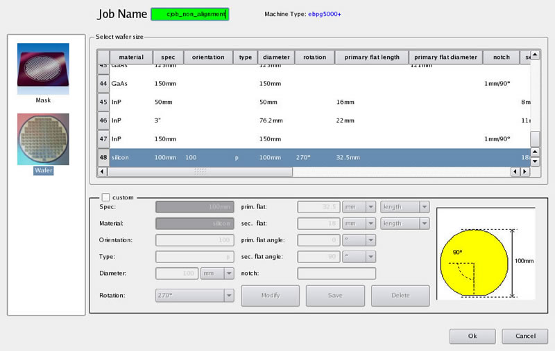
The SUBSTRATE block is the only block you can pick up to start with. Drag and drop this box into panel 2. Immediately the window above opens. In this example we want to write on a 100µm wafer so Wafer is selected on the left hand side and then the last wafer definition (number 48) is selected from the list. Notice that the Job Name box is red until you fill in a valid job name. Click OK.
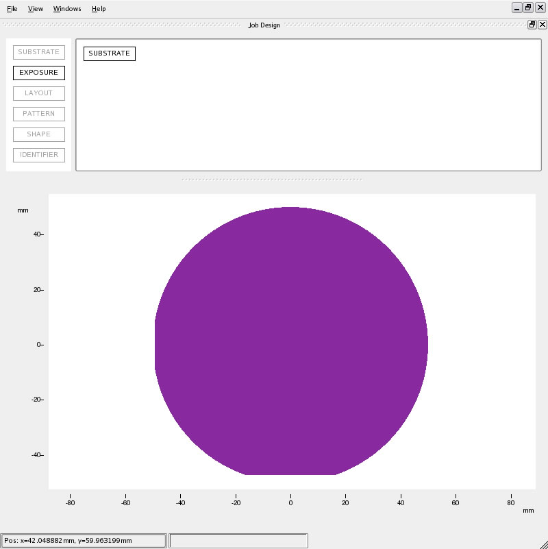
The cjob window now looks like this. The only building block that is now highlighted is the EXPOSURE block. Drag and drop this block on top of the SUBSTRATE block. This opens the following window.
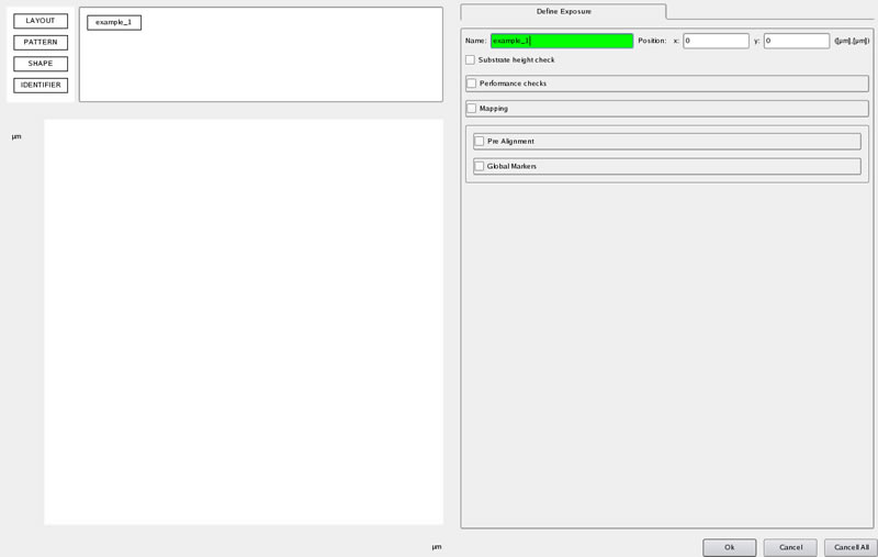
Fill in the exposure name. You can see that panel 1 is still here and if you want you can add (drag) the next block to panel 2 in this window, but in this example we click OK and return to the top level.
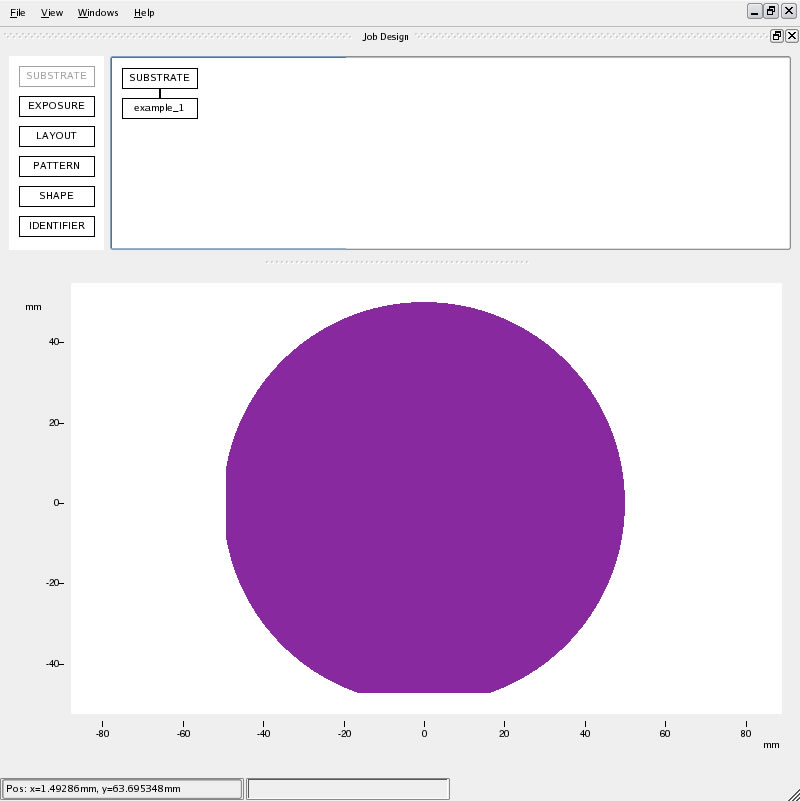
Substrate is now connected to example 1. All other boxes are now active. Drop the LAYOUT box on example_1.
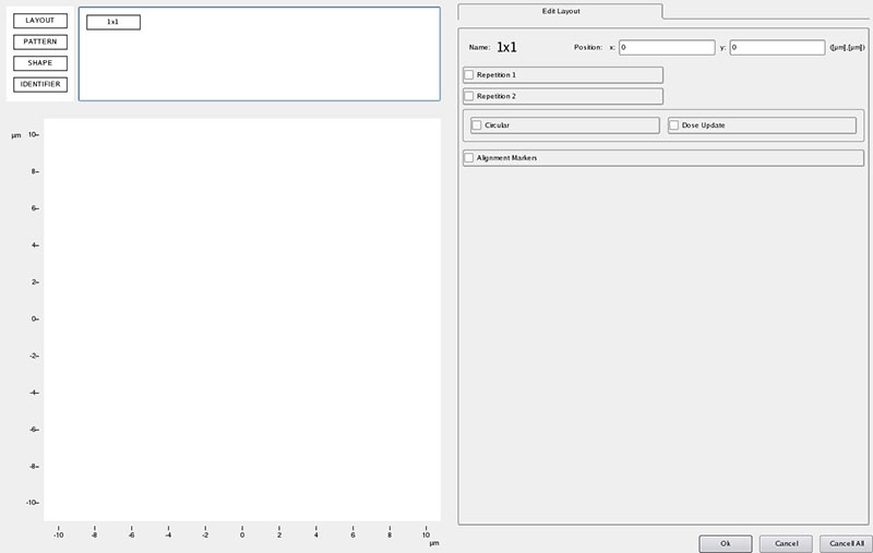
Leave all options unselected. Click OK. Now drop the PATTERN block onto 1×1.
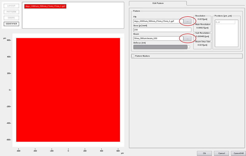
Click on the circled boxes to open a list of patterns in your pattern directory and available beams. Select the desired pattern file, dose and beam. Click OK.
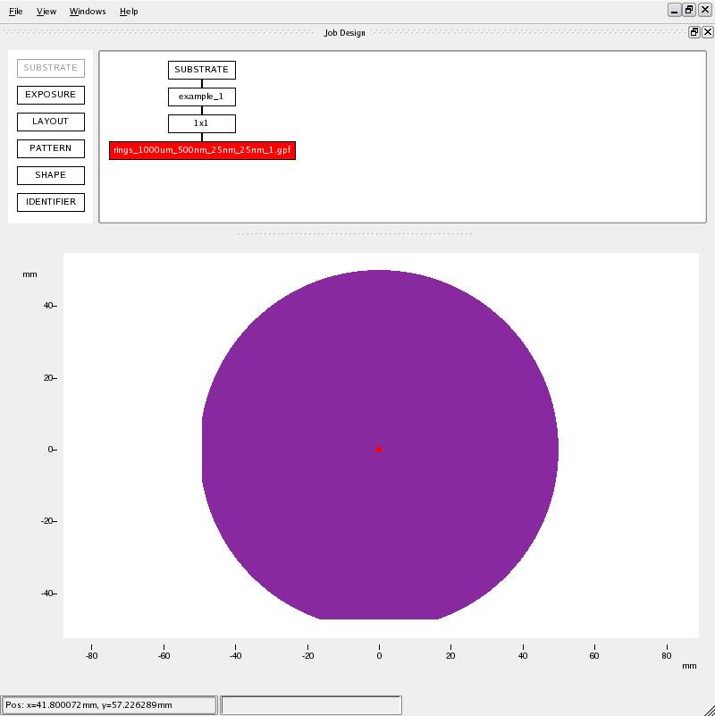
The layout is shown positioned on the wafer. To zoom in drag a box from top left to bottom right (zoom out is from bottom right to top left….just like cview) click to center. Place the mouse over the pattern and press Ctrl (on the keyboard) this pops up an information window.
CJOB example 2 – array
Here we use example 1 as the starting point
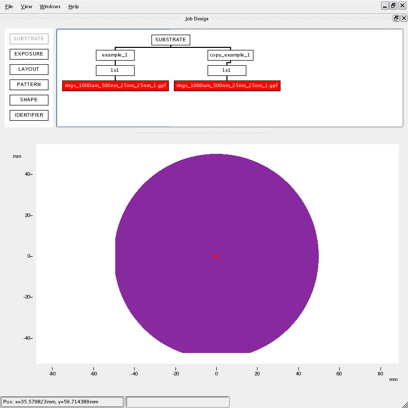
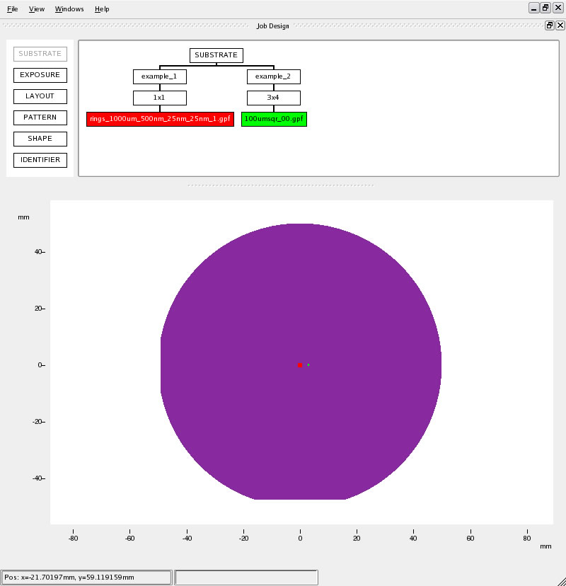
Right click the block example_1 and select copy, place the mouse over the SUBSTRATE block and paste. Double click copy_example_1 to open this block for editing and change the name to example_2. Double click the pattern block (rings_1000um_500nm_25nm_25nm_1.gpf) underneath example_2 and select pattern 100umsqr_00.gpf and 200na_300um.beam_100. Click OK twice to return the top level.
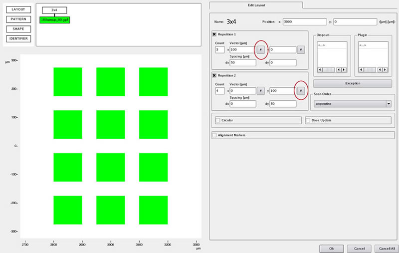
Click on the 1×1 layout block. Make the x position 3000µm. Select the Repetition 1 Repetition 2 boxes and fill in the Count numbers to create a 3×4 array. Press the two “#” boxes (circled), this automatically fills these boxes with the pattern size, then add in the space you want to leave between the patterns in the array in the Spacing boxes. NOTES: 1) the pattern size is automatically filled in only if there is a pattern block with a valid pattern attached to the layout box 2) CJOB supports non-orthogonal array definition which is why there are x and y boxes for each repetition vector. The example above is the normal way to define an orthogonal array. Click OK.
CJOB example 3 – dose test
Here we use example 2 as the starting point
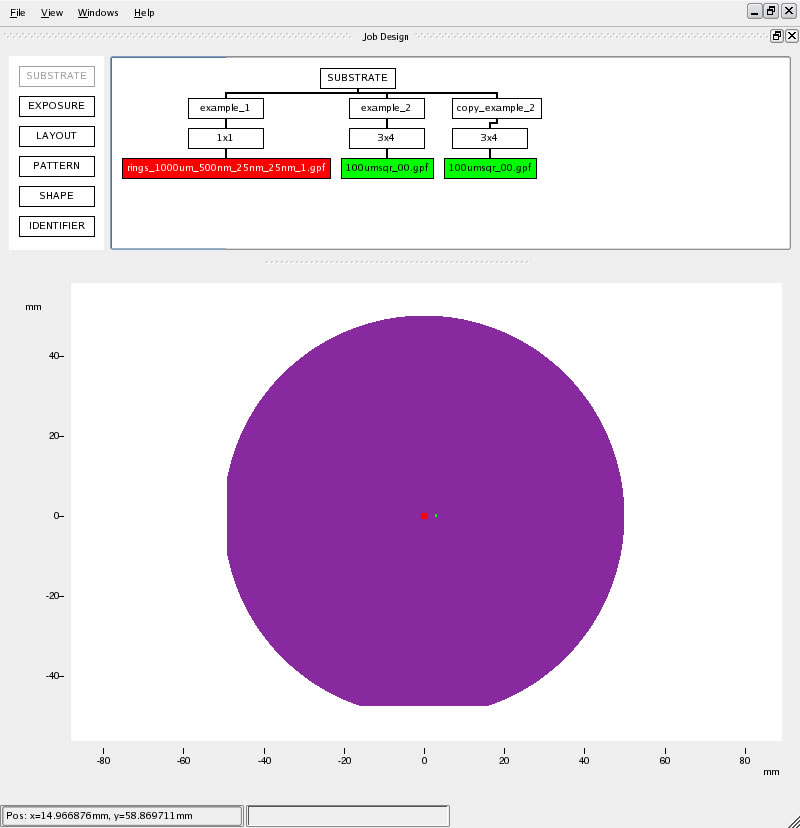
Click and drag the example_2 block onto the SUBSTRATE block (this is the same as copy-paste). Double click copy_example_2 and change the name to example_3. Double click the 3×4 block.
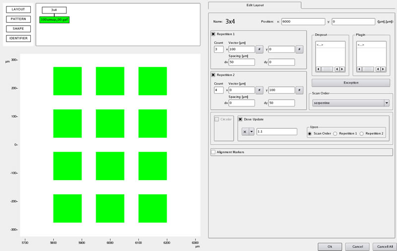
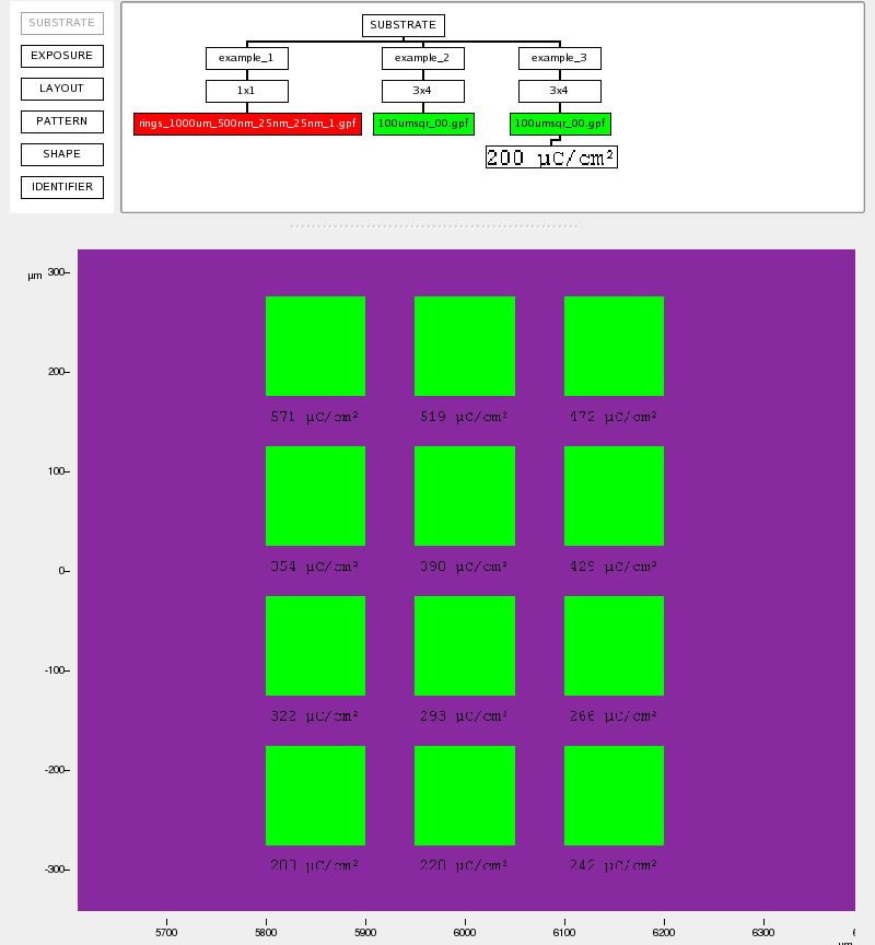
Change the x position to 6000µm. Select the Dose Update box and select X and enter 1.1 (this gives a 10% increase in dose per pattern) and press return. Move the mouse into the graphics window and over the bottom left pattern and press Ctrl, you should see a pop up information box. Move the mouse over other patterns in the array and you’ll see that the dose value is changing for each pattern. Drag and drop the IDENTIFIER block on top of the pattern block.
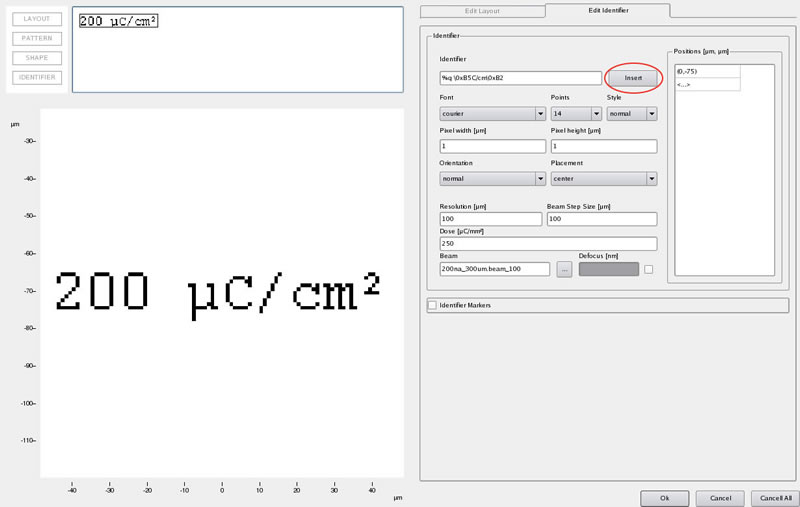
Select Insert and then Dose. Fill in the other parameters as shown above. Click OK twice to return to the top level.
CJOB example 4 – nested array
Here we use example 3 as the starting point.

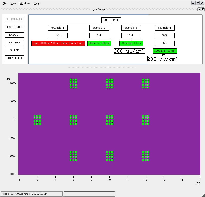
Copy example_3 block onto the SUBSTRATE block and change the name to example_4. Add a new LAYOUT block from panel 1 onto example_4. Click OK.
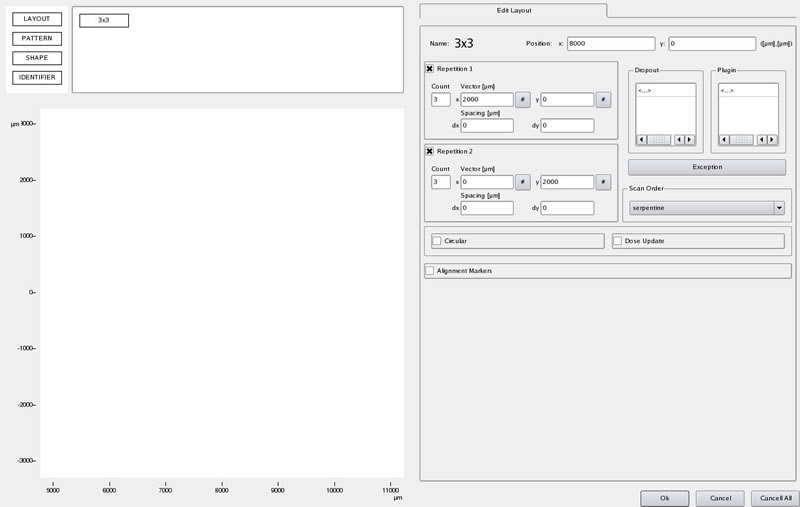
Make a 3×3 array, with vectors of 2000µm x and y with the x position 10000µm for this layout. Click OK.


Move the 3×4 block onto the 3×3 block, then delete the original 3×4 array. Edit the 3×4 array (under the 3×3 array) and change the position to 0,0. Example_4 should now look like the bottom picture here.
CJOB example 5 – exceptions (dropout and plugins)
Here we use example 4 as the starting point.
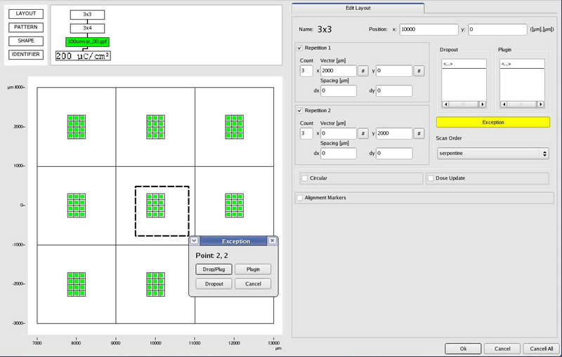
Copy example_4 block onto the SUBSTRATE block and change the name to example_5. Open the 3×3 layout block for editing. change the Position to x=10000µm, y=6000µm. Select the Exception button, then while pressing the Ctrl key drag a box over cell 2,2 (center array shown above) in the graphics window. In the pop-up window select Drop/Plug. Deselect the Exception button.
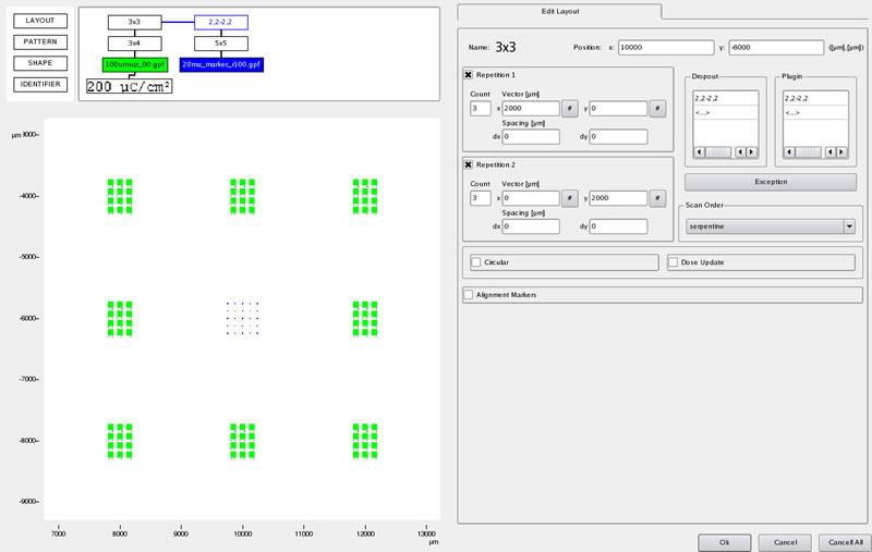
A blue box called 2,2-2,2 will appear. Underneath this added a 5×5 array and the pattern shown (Dose=200mC/cm2, Beam=200na ). The spacing between patterns in the 5×5 array shown is 100µm. Return to the top level.
This is the end of the examples of Cjob layout for non-aligned patterns. Hopefully you will now understand the general concepts behind cjob. You should now play with some of these examples and look at some of the different options not used in these examples. You can see that with the use of nested arrays and exceptions that your layouts can become VERY complex, you’ll find that this is rarely necessary, but these techniques are very useful to know and understand.
Extra
Here I’ve put an extra cjob exposure that is a form of job that is commonly used. In order to reduce job times it is common to split the writing of your design into 2 gpf files that have different resolutions and are written with different beams. Below is a simple cjob file to write these two patterns.
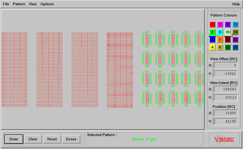
Above is an example of a pattern that has been split into large (green) and small (red) features.
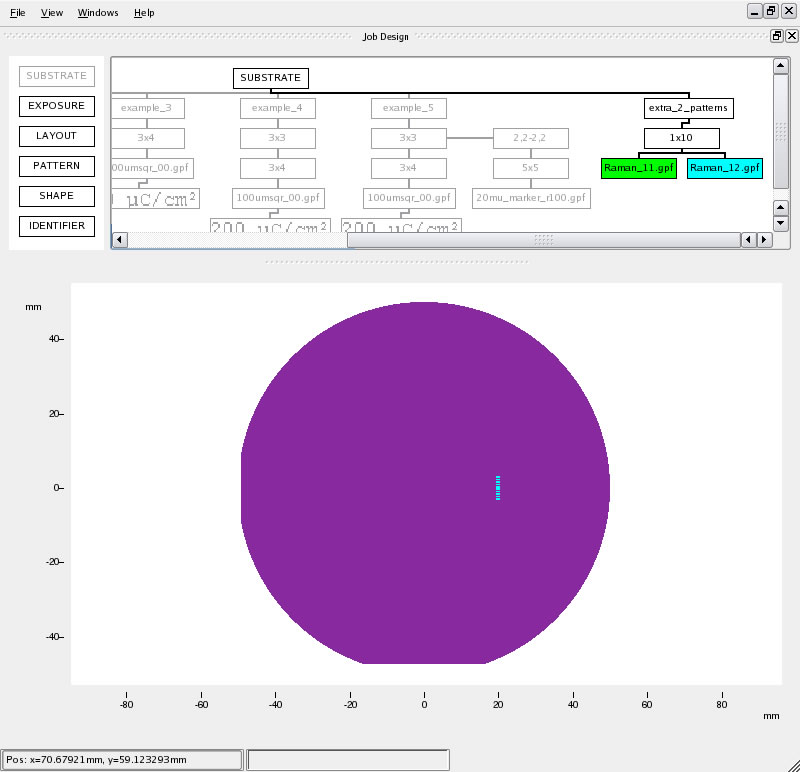
Here both patterns have been attached to the same layout box, so they both get the same array information.
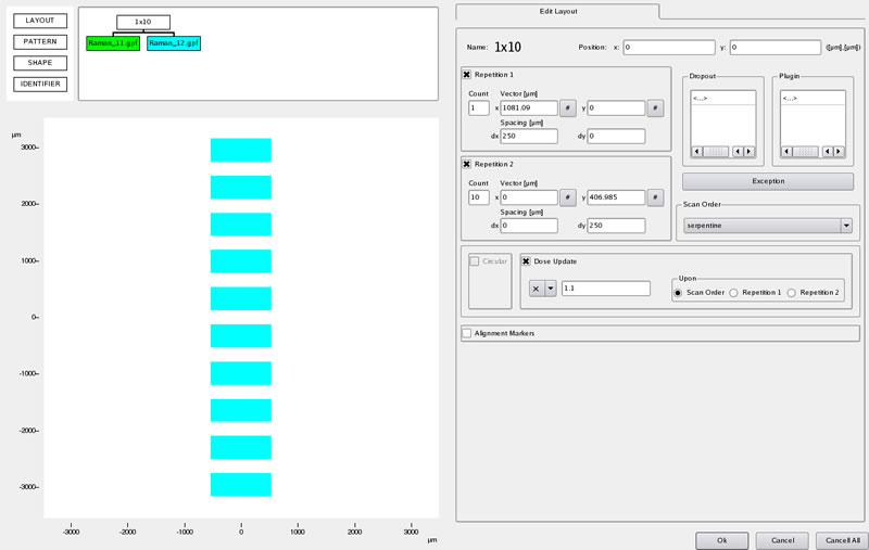
BUT be careful. This layout contains a dose update parameter (10% increase per array element) and this applies to both patterns attached to it.
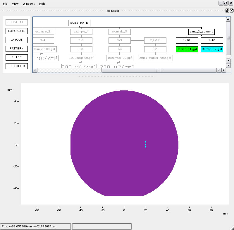
If you want to perform a dose update on one pattern but not on the other, the layout above is a good solution. Here the dose update in the 1×10 array attached to Raman_12.gpf has been removed, but because they are still attached to the same exposure block they will be exported as a single .job files by default.