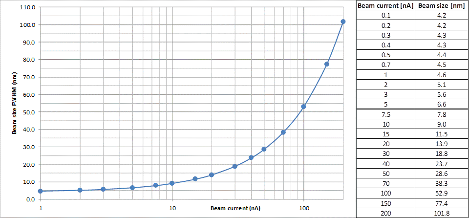
The electron beam in our system is Gaussian with circular cross-section resulting from the use of the circular aperture. The size (FWHM) of the beam depends on the current. On our tool, users can select current from 100pA to 200nA, the spot sizes vary from 5nm to 100nm. The size of the beam does not necessarily imply that the beam will create the same size feature in resist. The size of the exposed feature after develop will also depend on the dose used. The FWHM of a gaussian beam is effectively a 2sigma value, and if the processing level is selected below the FWHM threshold (overexposure), the printed feature will be larger, and if the processing level is selected above the threshold (underexposure), the printed feature can be smaller.
While any beam current in the specified range can be created, to keep things practical, we maintain (weekly calibrate) a finite set of selected beam currents and users choose from this set. The table below lists all available beams.
Beam current and beam size

Resolution, pixel size, grid
During the exposure, the selected beam is stepped through every pixel of a pattern to be exposed. The size of the pixel (also referred to as “resolution” or “grid”) is chosen by user during the data fracturing process (conversion from .gds format to .gpf format that the ebeam tool uses). The value of the pixel can be selected between 1nm and 100nm.
The writing strategy dictates that the beam must be stepped through every single pixel of the layout to be exposed. The selected size of the pixel thus have an impact on the total number of pixels that need to be visited by the beam and consequently on the total write time.
More importantly, the selected pixel size has a large impact on image quality. The image quality depends on the combination of selected pixel size (selection made during data preparation step) and selected beam size (selection made at the beginning of the exposure of the job). Users have a complete freedom to use any possible combination of pixel size and beam size, provided that the combination does not lead to the writing frequency exceeding the maximum frequency limit the electronics of the tool can handle. The maximum frequency of the system is 50Mhz.
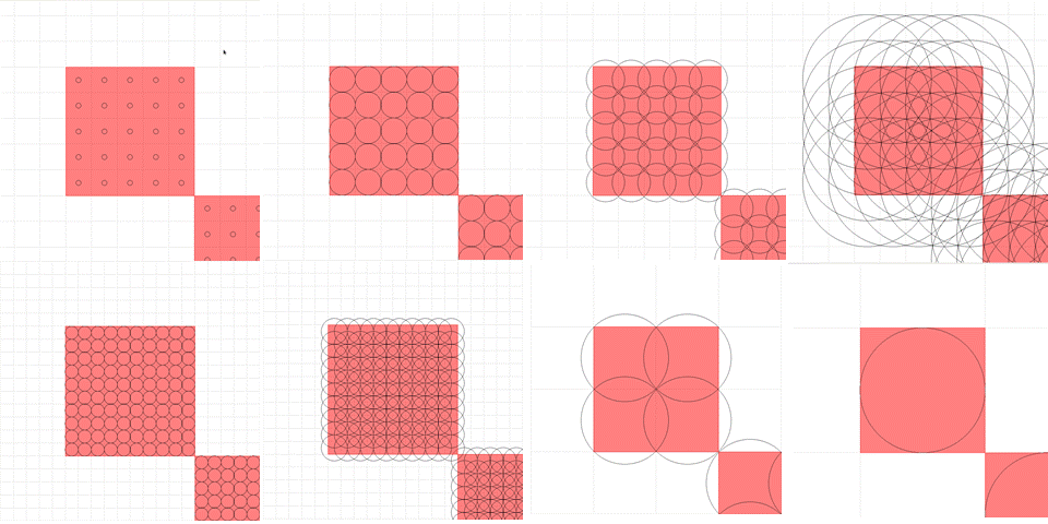
Beam size vs Pixel size

The image shows several possible combinations of beam size and pixel size. If the beam is chosen sizably smaller than the pixel size, the result will be an array of holes written in the resist. If the beam size matches the pixel size, the resulting features will be close to the intended image size (provided a proper dose is selected as well), but the line edge roughness may be a bit too high for some desired applications (e.g. optical waveguides), and some resist “scumming” (leftover resist residue between individual shots) may be present after develop. If the beam size is selected significantly larger than the pixel size, the printed feature will be oversized by the corresponding amount, the corner rounding will be larger, but the edges will be much smoother and the resist scumming will be minimal or none. To achieve clean well defined pattern, one would typically select a beam of slightly larger size than the pixel. To achieve smooth edges, one would select smaller pixel size, and possibly significantly larger beam size.
The user is the person who understands the needed lithographic quality and it is he/she who must decide on the necessary compromise between quality and writing time.
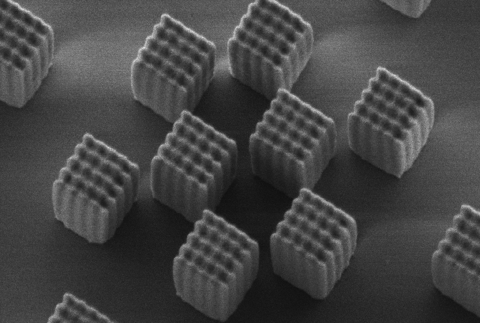
Can the individual ebeam shots be seen?

The beauty (and sometimes a curse) of ebeam lithography is that everything can be clearly seen in the results on the wafer. This image shows every individual shot delivered by the tool to a negative tone resist. The size of the beam has been selected to be a bit smaller than optimal, and the pattern was slightly underexposed to emphasize the effect.