Please use the Service request interface to make a dicing request.
Step-by-step user manual available here.

- DO NOT USE THE MACHINE BEFORE HAVING THE COMPRESSED AIR ON.
- Never put hands in the area of the blade and of the chuck!
- Rotations reminders:
- 30000 rpm for Silicon
- 25000 rpm for glass materials and ceramics
- Cut speed:
- 5 mm/s for silicon
- 1 mm/s for glass materials and ceramics
Contents:
- Dicing and blades overview
- Get sample ready for dicing
- Allowed materials and available blades
- How to use the system
I. Dicing and blades overview
Dicing is used for cutting partially (scribing) or completely (singulation) a wide range of materials such as semiconductor compounds, ceramics, various glass types, composites… If the blade and the dicing parameters are correctly selected according to the specificity of the material to cut, perfect edges can be created, even for very hard and brittles materials.
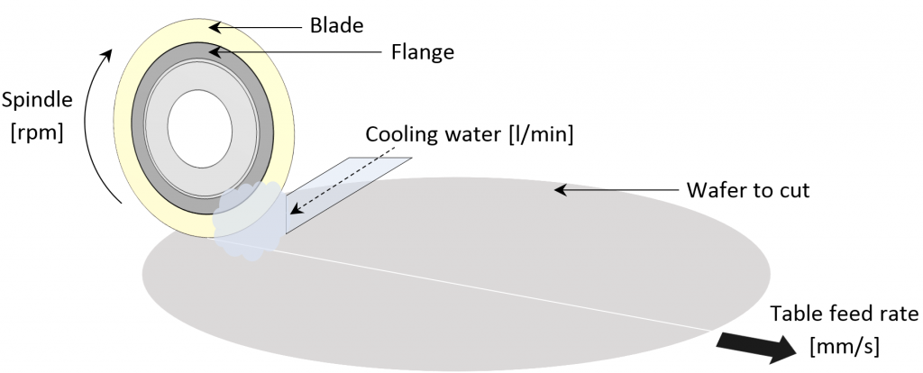
Dicing blades have diamond particles embedded in a bond matrix. They hold together with a binder of either resin bond (soft strength), sintered metal bond (medium strength) or electroplated nickel bond (hard strength). During dicing, each diamond particle embedded in the blade slowly breaks/shatters as it grinds away material from the substrate, and new particles captured in the matrix continuously offer new sharp point until the blade wears out. The concentration and the size of the diamond particles, together with the type and the thickness of the matrix, make the structure of the blades and have a direct impact on the finish quality of a cutting job.
As a consequence, the materials to cut will have a strong impact on the selection of the correct types of dicing blades.
For hard and brittle materials (e.g. sapphire), soft bond dicing blades, such as resin bond, are usually recommended, whereas a harder bond material, such as electroplated nickel bond, will be preferred for softer materials.
Comparatively to the material to cut, a bond matrix that is too soft may release diamond particles at an excessive rate and may wear out very fast (short lifetime). On the opposite, a bond matrix that is too hard will result in a low amount of released diamond particles and hence in low cutting ability; regular dressing of the blade will be needed to constantly expose next layers of fresh and sharp diamond particles.
During dicing, the high rotation speed of the blade and the strong friction of the diamonds particles on the diced substrate generate an important amount of heat which is important to evacuate. Cooling water is supplied at close proximity of the dicing blade in order to thermally stabilize the process and to enhance blade lifetime.

II. Get sample ready for dicing
- Alignment marks
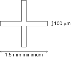
For dicing across full length of the substrates and for properly aligning with the structures, it is recommended to have dicing aligning marks. To ease the alignment procedure, it is important to have the marks visible by eye. In order to nicely match the vision capacity of the dicing tool as well, do not exceed the following dimensions:

- Surface protection
It is heavily advised to protect sensitive structures that may be damaged during the process (water supply + creation of particles or “mud” during dicing).
Protection with photoresist works, as long as thick enough to nicely cover the structures and as long as great care is taken to promote correct adhesion of that resist to the substrate. Poor adhesion of the resist on the substrate will lead to peel-off during the dicing process (because of the pressured water supply!) and will not help.
CMi recommends : - <9 um topography :
AZP4K-AP (click for process details) - >9um topography :
AZ10XT-60 (click for process details)
When the dicing is complete, the protective resist is wet-removed in Z2 – UFT Resist. Wet removal of the resist allows to properly lift-off trapped particles and to recover a spotless surface after dicing.
It is mandatory to remove the UV-Tape before stripping !!
Holders for chips, 1/4, 1/2, and full wafer are available (list here).
III. Allowed materials and available blades
Allowed materials
Standard :
- Silicon
- Glass materials
- Metals : only deposited layers, several microns only. No bulk metals!
Not standard :
- Sapphire
- Ceramics
- Ferrites
- Stack glass/silicon
- Epoxy (SU 8)
| Blade bond type | Blade thickness [mm] |
Flange/blade outer diam. [mm] |
Max allowed thickness to cut [mm] |
|---|---|---|---|
| Resin | 0.25 | 51/56 | 1.5 |
| Resin | 0.07 | 51/54 | 1 |
| Resin | 0.25 | 50/56 | 2.5 |
| Nickel | 0.1 | 49/52 | 1 |
| Nickel | 0.03 | 49.4/52 | 1 |