Contents
I. Introduction ↑
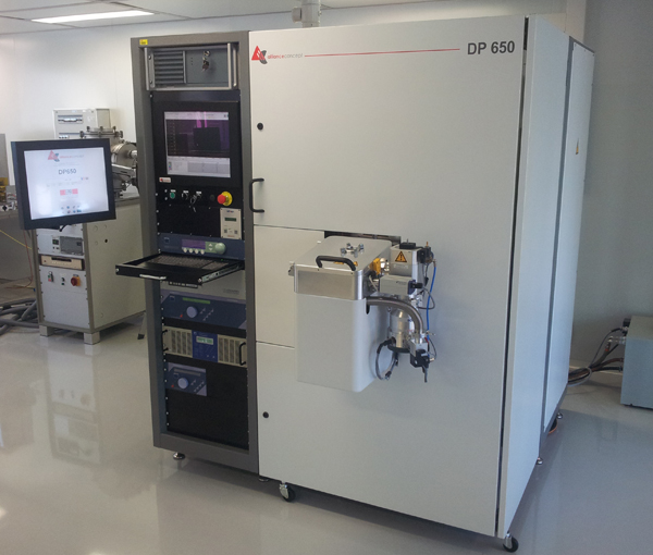
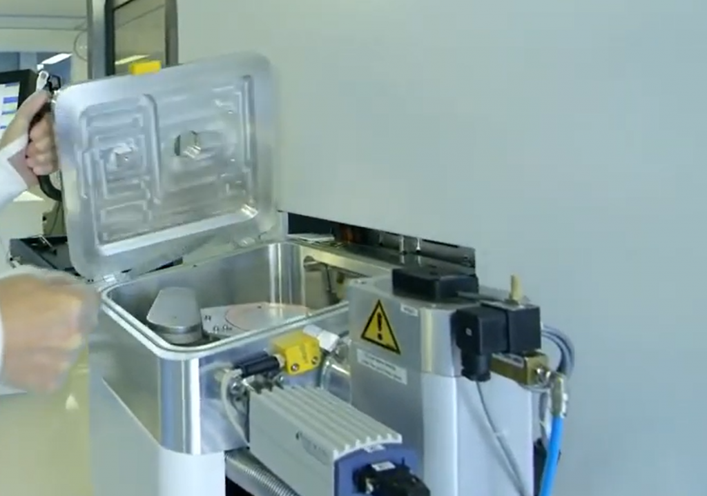
The DP 650 is a sputtering machine allowing the deposition of metallic or dielectric materials.
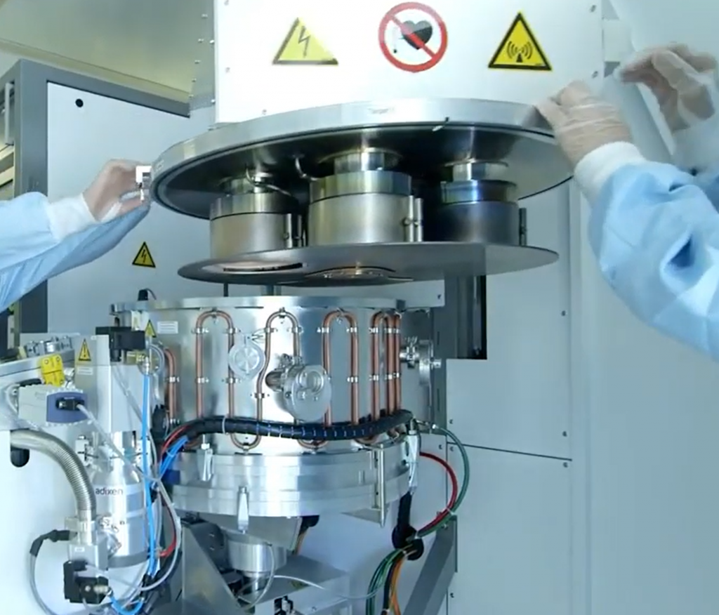
The tool is composed of one unique chamber with 6 magnetrons and a loadlock. With 6 x 100 mm targets installed in the system, a stack of (up to) 6 different materials can be deposited without unloading of the sample.
Note : It is important to note that magnetrons are not installed in co-sputtering configuration.
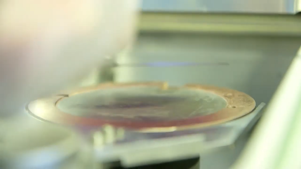
A plate is used as a carrier and loaded / unload in the chamber at beginning / end of a process. Samples which can be coated are:
- Chips : No carrier wafer required.
- 100 mm wafers: As standard.
- Maximum height accepted : 5 mm
The configuration of the system is :
- 2 x RF magnetrons (With gas injection rings close to the targets – Also configurable in DC):
- Cathodes #1 & #2 : Oxides, Nitrides, Metals
- 4 x DC magnetrons:
- Cathodes #3 to #6 : Metals, Semiconductors
For more details, see Available PVD targets in CMi page.
II. Equipment description ↑
Loadlock
The transfer robot is located into the loadloak. On the fork of this robot sits a carrier plate. It is on this carrier that the sample will be placed. At the beginning of process, the carrier is loaded in the chamber and it is unloaded only when the process is finished.
The capability is max. 100 mm wafer at a time.
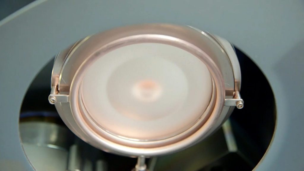
Substrate holder station
In the chamber, there are 2 posts:
- Cold post: For processes at room temperature (RT).
- Hot post: For processes at high temperature (HT).
- Temperature max. 400°C.
- Possibility to define temperature profiles.
Substrate holder polarization (RF Bias) for activation / cleaning / densification:
- RF generator max. 300W @13,56 Mhz.
Pumping
Pumping in the system is achieved by:
- Loadlock:
- Primary pump : Dry pump – Pfeiffer-Adixen ACP 15
- Secondary pump : Turbo pump – Pfeiffer-Adixen ATP 80
- Chamber:
- Primary pump: Dry pump – Pfeiffer-Adixen ACP 40
- Secondary pump : Cryogenic pump – CTI ON-BOARD 8
Pressure
The control of the pressure in the chamber is achieved by a throttle valve [0-100%].
Vacuum levels.
- Chamber :
- 1 x Full Range Gauge: INFICON BCG450
- 1 x Capacitance Diaphragm Gauge: INFICON CDG045D
- Loadlock : < 1.10-6 mbar, gauge INFICON – BCG450 ATM to Ultra-High Vacuum Triple-Gauge.
Gas
3 different gases are available:
- Ar : Mass flow controller (MFC) [0-50 sccm]
- N2: MFC [0-5 sccm] & MFC [0-50 sccm]
- O2 : MFC [0-5 sccm] & MFC [0-50 sccm]
Sources & Magnetron
DC and RF generators are :
- Source:
- DC generator “Huttinger TruPlasma 3002” : Max. power 2 kW.
- RF generator “Huttinger PFG 600 RF” : Max. power 600 W @ 13,56 Mhz.
- Bias
- RF generator “Huttinger PFG 300 RF” : Max. 300W @13,56 Mhz.
6 x RF/DC magnetrons : plane, circular, for 100 mm targets.
Phase shifter “Huttinger MOP” for RF matching Source / Bias.
III. Recipes ↑
The preliminary cleaning of samples can be done in-situ by ionic bombardment just before the deposition. In certain cases, this operation is important to guarantee a good adhesion and/or remove native oxide.
Excepted the process duration, parameters of recipes can not be modified by the user.
Note: For the creation of new recipes, please contact responsibles of the equipment.
| Recipes Labelling | |
|---|---|
| RT = | Room Temperature |
| HT = | High Temperature |
| U = | Uniform |
| F = | Fast |
| S = | Slow |
| VS = | Very Slow |
| E = | Ar Etching |
| O = | Oxidation |
| A = | O2 Activation |
| M = | Mix between different layer types (U+S; U+F;…) |
| Step | Etch rate [nm/min] | Thin-Film |
| RTU_E120 | 1 | SiO₂ Wetox |
For details concerning precious material billing, see Processing fees page.
IV. How to use the system ↑
All the actions to operate the system are detailed in the user manual.
