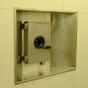


For transparent substrates: a dummy wafer has to placed bellow the process wafer in the same slot of the cassette to allow the detection of the sample during the transfer.
In case of thick samples or two wafers loaded in the same slot of the cassette, the slot right below has to remain empty to allow a proper loading in chambers.
Contents
I. Introduction ↑
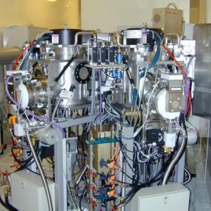
The SPIDER 600 is a cluster tool which allows the deposition of metallic or dielectric materials on wafers by RF, DC or pulsed DC sputtering. The sputtering is a phenomenon in which atoms are ejected from a surface after its bombardment by energetic particles.
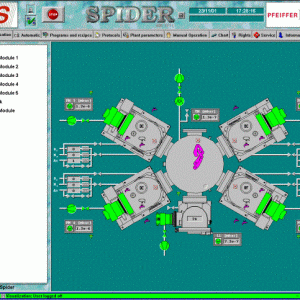
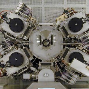
The tool is equipped with 4 chambers (Process modules – PM) and a loadlock connected to a transfer module. A robot is in charge of transfers and allows the deposition of (up to) 4 different materials without exposure of the sample to the atmosphere. Each chamber is equipped with a planar 200 mm target.
Samples which can be coated are:
- Chips : A carrier wafer is required.
- 100 mm wafers: As standard.
Note : The SPIDER 600 has been designed to be also compatible with 150 mm wafers. However a risky conversion of the tool is required. For this reason, this configuration is not proposed.
The configuration of the system is :
- 1 x RF chamber (can also be configured in DC):
- PM1 : Oxides, Nitrides (Reactive sputtering)
- 3 x DC chambers:
- PM2 : Nitrides (Reactive sputtering)
- PM3 : Metals, semiconductors
- PM4 : Metals
For more details, see Available PVD targets in CMi page.
II. Equipment description ↑
Loadlock
In the loadlock, a 25 wafers cassette can be found and sequences of deposition (defined by a recipe) can be set individually for each slot.
Transfer module
The transfer is the different chambers is achieved by a robot located at the center of the transfer module. The tool is able to process in parallel wafers depending on the availability of chambers and the sequence of deposition desired by the user.
Substrate holder
Substrate holders can be heated up:
- Temperature max. 350°C
- Possibility to define temperature profiles.
Substrate holder polarization (RF Bias) for activation / cleaning / densification:
- RF generator 300W @13,56 Mhz.
Pumping
Pumping in the system is achieved by:
- Primary pump (Diaphragm pump) MVP 100 for each process chamber, transfer module and loadloack.
- Turbo pumps:
- Pfeiffer TMH 521 for each chamber and the transfer module.
- Pfeiffer TMH 261 for loadlock.
Pressure
Each chamber is equipped with a throttle valve (3 positions : Open, Center or Closed). The “center” position gives a pressure ~ 5.10-3 mbar with Ar flow 15 sccm.
Vacuum levels:
- Process chambers : < 5.10-7 mbar, gauge PKR 251.
- Transfer module : < 1.10-6 mbar, gauge PKR 251.
- Loadlock : < 5.10-6 mbar, gauge PKR 251.
Gas
3 different gases are available:
- Ar [0-200 sccm]
- N2 [0-100 sccm]
- O2 [0-50 sccm]
Sources & Magnetron
DC / Pulsed DC and RF generators are :
- Source:
- DC generator “Maris” : Max. power 3 kW.
- Pulsed DC generator “Pinnacle” : Max. power 5 kW, 5kHz-350kHz.
- RF generator : Max. power 1200 W @ 13,56 Mhz.
- Bias:
- RF generator 300W @13,56 Mhz.
One magnetron RF/DC per process module : plane, circular, rotating field for 200 mm diameter targets (Typical uniformities: ± 5% on 100 mm wafer, ± 8% on 150 mm wafer).
A synchronization oscillator for the matching of RF source and RF bias in PM1.
- Deposition chamber
- Gate (Transfer module /chamber isolation)
- Throttle valve
- Turbo pump
- Isolation valve (Primary pump / Secondary pump)
- Primary pump (Diaphragm pump)
- Exhaust
- Substrate holder
- Wafer
- Heater
- Substrate holder cooling circuit (Cold water or hot wafer)
- Target
- Magnetron
- Target cooling circuit (Cold water of hot water)
- N2 line
- O2 line
- Ar line
- Venting valve (N2)
- N2 mass flow controller
- O2 mass flow controller
- Ar mass flow controller
- Ar injection valves
- Vacuum measurement
- Chamber cooling circuit (Cold water of hot water)
- DC generator
- Pulsed DC generator
- RF generator (Only PM1)
- Matching box (Only PM1)
- Automatic switch
- RF generator (for RF bias)
- Matching box
III. Standard recipes ↑
To guarantee the quality of the material deposited, a cleaning of the target is highly recommended. A first deposition can be done on a dummy wafer for this purpose. Recipes are named Target_clean_xxx.
The preliminary cleaning of samples can be done in-situ by ionic bombardment just before the deposition. In certain cases, this operation is important to guarantee a good adhesion and/or remove native oxide.
Apart from process duration, all parameters of “standard” recipes are locked. Some unlocked recipes exist and are considered as “under development” (not guaranteed by CMi).
ITO Deposition
A quantitative study has been done by KLA Corporation on ITO layers deposited by the SPIDER600. The publication can been found here :
Quantitative study of the thickness-dependent stress in indium tin oxide thin films
Etch rate table
| Recipe | Etch rate [nm/min] | Thin-Film |
| Etch_Ar-1 | 3 | SiO₂ Wetox |
For details concerning precious material billing, see Processing fees page.
IV. How to use the system ↑
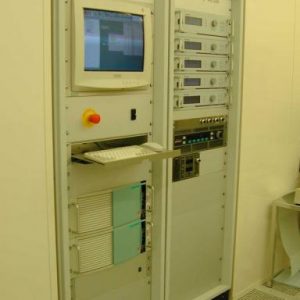
All the actions to operate the system are detailed in the user manual.
