Image Stitching Application
SmartStitch is a standalone application for the production of tiled images from a set of individual overlapping images captured via SmartSEM. The application may run in either online or offline mode. The online mode is available on the SEM Crossbeam computer (Zone 15), it means it will provide the ability to automatically configure and execute a Stage Scan procedure by communicating directly with SmartSEM.
Once a set of images has been acquired, SmartStitch provides the ability for the relative positions of the individual images to be adjusted, either manually or in a semi-automated manner, in order to produce a high-quality montage. The montage may then be saved as a new image.
In offline mode, the Stage Scan features are disabled and only image stitching may be performed. The offline mode is available on the SEM Metrology computer in room BM1.132.
Features
- Define the overall scan area and display a background preview image
- Specify the number of scan fields manually, or select magnification to calculate automatically
- Specify the amount of overlap between scan fields
- Select choice of scan pattern
- Optionally use beam shift instead of stage movement at high mag
- Edit the scan area to include/exclude fields or groups of fields
- Move the stage to any selected field
- Grab an image from SmartSEM at the current field
- Auto-grab images for all scan fields, using the chosen scan pattern
- Automatic focus options for large scan areas
- Capture from multiple channels where supported by hardware
- End of scan options, e.g. blank beam or turn EHT off
- Choice of user interfaces – guided mode or advanced
- Pan or zoom the composite image
- Switch between channels if multiple channels were captured
- Manually move individual image tiles using the mouse or keyboard
- Transparent overlay effect to assist manual placement
- Automatic stitching of all image tiles or an individual tile
- Stitching is non-destructive – no image data is changed
- Image display quality automatically adjusts to available hardware
- Numerous configuration options for optimising automatic stitching
- Lock or unlock individual image tiles to prevent movement
- Import and stitch image tiles from existing data
- Export montage to a new composite image
- Automatic background contrast adjustment
- Choice of user interfaces – guided mode or advanced
Presentation
Software icon to launch the software.
Screen layout
The screenshot below shows the general layout of the SmartStitch screen.
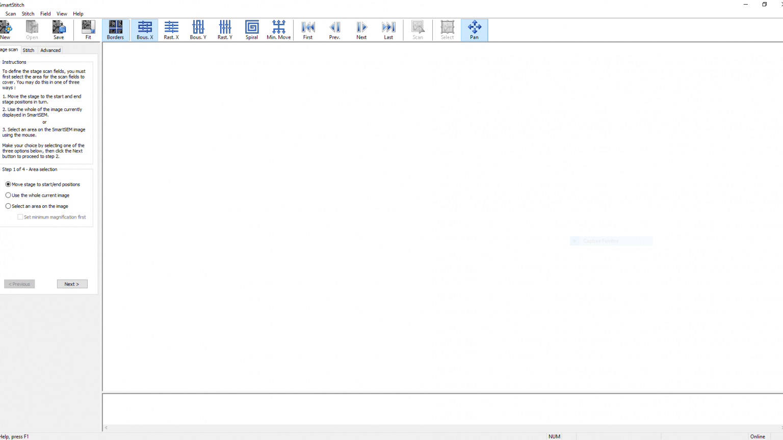
At the screen's top, you will find a traditional menu and toolbar setup. The toolbar buttons act as convenient shortcuts to frequently-used menu options. Moving to the left side of the screen, you'll come across the control panel, which serves as the primary interaction hub. This control panel has three tabs at the top, allowing you to switch between different modes such as stage scanning and image stitching, or to access advanced settings. If the application is running offline, without SmartSEM, the stage scan tab won't be visible. Located at the bottom of the screen is a scrollable logging area. This area is used for providing feedback and may also display error codes or diagnostic information in case of unexpected issues. The central and most substantial portion of the screen serves as the primary workspace. Here, image tiles will be displayed as a montage as they are acquired from the microscope or imported from disk. More detailed information about each of these screen areas will be covered in subsequent sections.
At the screen’s top, you will find a traditional menu and toolbar setup. The toolbar buttons act as convenient shortcuts to frequently-used menu options.
Moving to the left side of the screen, you’ll come across the control panel, which serves as the primary interaction hub. This control panel has three tabs at the top, allowing you to switch between different modes such as stage scanning and image stitching, or to access advanced settings. If the application is running offline, without SmartSEM, the stage scan tab won’t be visible.
Located at the bottom of the screen is a scrollable logging area. This area is used for providing feedback and may also display error codes or diagnostic information in case of unexpected issues.
The central and most substantial portion of the screen serves as the primary workspace. Here, image tiles will be displayed as a montage as they are acquired from the microscope or imported from disk. More detailed information about each of these screen areas will be covered in subsequent sections.
The Control Panel
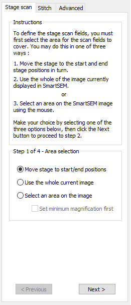
The control panel, situated on the left side of the main workspace, provides a straightforward way to toggle between stage scanning and image stitching modes. You can easily switch between these modes by selecting the respective tab whenever needed. An example of the control panel view is displayed above.
It’s important to note that there are two control panel layout options, catering to individual preferences. The example illustrates the initial step in the stage scanning process using the ‘guided mode’ interface, consisting of four steps that can be navigated using the Next and Previous buttons located at the control panel’s bottom, as demonstrated.
Alternatively, selecting the ‘Advanced user interface’ option from the View menu condenses all four steps into a single panel. This mode is designed to offer a more convenient interface for experienced users.
A similar difference exists on the image stitching tab, where the ‘guided mode’ comprises two panels, while the advanced mode is a single panel. Unlike the stage scan panels, the advanced stitching panel provides greater control over the configuration of the stitching process.
You have the flexibility to switch between ‘guided’ and ‘advanced’ views at any time. You can seamlessly transition from following the guided stage scanning procedure to utilizing the advanced image stitching interface, or vice versa.
The logging area
At the bottom of the main workspace is a resizable logging area, which is used to feed back information to the user during the stage scanning and image stitching procedures. The type of information displayed in the log includes success/failure of stitching for individual image tiles, display of stitching confidence percentages, display of filenames loaded and saved, and any error messages that require user attention.
The main workspace
The central area of the SmartStitch display serves as the primary workspace. It is where the composite image montage is presented and where users interact using the mouse and/or keyboard.
In stage scan mode, after moving through the wizard, the main workspace displays a grid of fields that represent the presently chosen scanning parameters. Additionally, a red marker follows the stage’s position, allowing users to correlate the current SmartSEM image with the overall display. An illustration of this is provided below for reference.
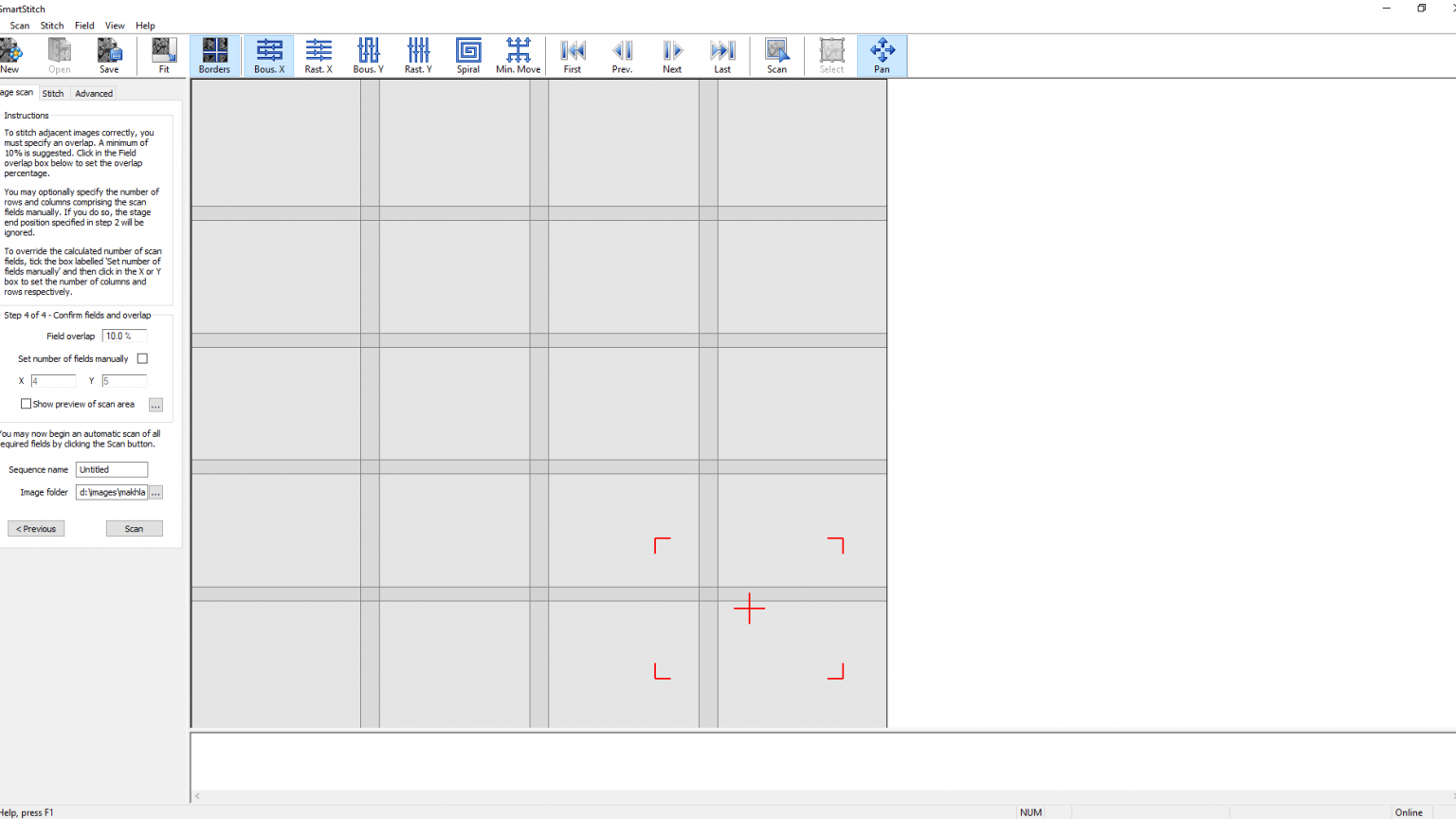
The provided screenshot offers a view of a grid consisting of 5 rows and 7 columns of scan fields, each with a 10% overlap. Within this grid, the red cross signifies the stage’s current position, while the red corner markers define the current field of view on the sample. It’s worth noting that if beam shift is employed, these markers may not align as depicted above. However, the red cross consistently represents the stage’s position, and the corner markers adjust according to the current beam offset.
When an auto-grab process is initiated, the primary workspace dynamically updates as the stage scan progresses. The red stage position indicator and corner markers move in sync with the stage’s motion, or if beam shift is automatically adjusted. At each field stop, an image is captured from SmartSEM and displayed in the corresponding position within the primary workspace. This process allows you to witness the gradual assembly of the complete image as each field is populated.
In image stitching mode, the primary workspace maintains a similar format, although the stage position indicator is omitted, and any unoccupied scan fields are disregarded. The image tiles are presented according to the Stage XY information within the TIF headers, which may not always result in a perfect alignment due to constraints on the precision of mechanical stage movement and potential discrepancies between stage coordinates and pixel size encoded in the images, such as from incorrect magnification calibration or hysteresis correction.
An illustration of the primary workspace in image stitching mode is provided below.
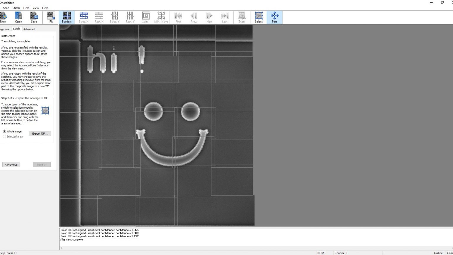
The provided screenshot illustrates a grid of images, arranged in a 5 x 5 pattern, with each image having dimensions of 1024 x 768 pixels. These images collectively cover the surface of a Si etched design.
To maintain responsive performance and avoid potential slowdowns caused by the simultaneous display of a large number of images, the quality of the composite image presented in the main workspace is automatically adjusted. Importantly, this adjustment doesn’t compromise the accuracy of image stitching or the quality of the montage when saved to disk.
You can configure the image quality displayed in the main workspace by utilizing the relevant option found on the Advanced tab within the control panel. An example of this configuration is provided later in the page.
Description of menus and toolbar
Menu items
The main menu consists of six sub-menus:
- File,
- Scan,
- Stitch,
- Field,
- View,
- Help.
Individual menu items are also provided by a toolbar button, the button image is shown below.

New
Discards all data in the main workspace and begins a new session. If images have been added to the workspace, you will be prompted to save any changes before the area is cleared. Note that no image tiles are ever deleted from disk or changed in any way by the SmartStitch application.
Open
Only enabled when in stitch mode, this option opens a set of previously saved images to allow further stitching and/or export. If any of the original image data has been moved or deleted from the original location, then those particular images will not be displayed.
Save
Saves the current status of the stitching process to a disk file. This file records the names and disk locations of the original image tiles, along with their adjusted positions as a result of stitching. No image data is saved – the original images remain untouched in the SmartSEM image folder.
Save As
Provides the same function as Save but prompts for a new file name or location.
Import images
Only enabled when in stitch mode, this option N/A allows import of one or more CZ format TIF files
for stitching.
Export montage
Only enabled when in stitch mode, this option N/A allows all or part of the montage to be saved as a
new TIF file. The exported file will contain a subset of CZ TIF data, such as the pixel size and
stage position, so that it is possible to add annotation at a later time.
Exit
Terminates the application.
General operations
The terms “online” and “offline” in SmartStitch refer to its ability to interact with the SEM. When SmartSEM is running during SmartStitch’s launch, it operates in online mode, allowing users to configure and execute stage scans within SmartStitch. In contrast, offline mode is used on a disconnected PC or laptop and provides only image stitching capabilities, omitting the Stage scan tab. The current mode is indicated in the status bar. A valid license is required for SmartStitch to run.
Guided and advanced user interface
SmartStitch provides a choice of user interfaces. The default interface is known as guided mode, which provides a number of prompts to take the user step by step through image acquisition (in online mode only) and image stitching.
The advanced user interface provides abbreviated displays on the control panel, which may be more convenient for the expert user. For image stitching, more functionality is provided by the advanced mode.
To switch between guided mode and advanced mode, use the option View->Advanced user interface from the main menu.
More details and specific screenshots for the guided and advanced user interfaces are given on demand.