Introduction to Variable Pressure (VP)
The SEM Zeiss Crossbeam is equipped with the VPSE (Variable Pressure Secondary Electrons) technology that we develop in this page. VPSE technology utilizes the introduction of a gas into the chamber at controlled pressures. The gas ionization acts as a conductor to neutralize the charges accumulated on the substrate. When the electron beam interacts with the gas, it creates ions and free electrons that neutralize any potential electrostatic charges on the sample. This interaction allows imaging of non-conductive samples without the need for a conductive coating, thus preserving the sample’s natural state.
What changes in VP mode
Most of the features in VP mode are the same as for the High Vacuum (HV) mode. The electron source remains at high vacuum to reduce the scattering of primary electrons as much as possible. However, the pressure within the specimen chamber can reach up to 60 Pa (even more in other systems), which marks a significant deviation from the high-vacuum environment typical of standard SEMs. This variation in pressure has important implications for imaging and analysis.
IMAGE PRESSION DIFFERENTIELLE
It is important to note that differential pumping creates a more delicate balance to maintain within the system. IGP pumps are more heavily relied upon to ensure a high vacuum level at the gun and column, while mechanical pumping at the chamber level is reduced to maintain a precise pressure and gas quantity to meet the conditions for optimal imaging in VP mode. Thus, the use of VP mode leads to faster wear of the ion pumps, which is why it is necessary to return to HV mode at the end of a VP session.
Principle
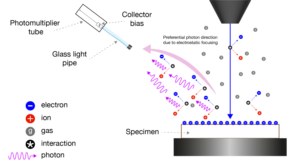
Generation of positive ions and their movement toward the negatively charged areas of the sample neutralize the negative charge accumulated at the specimen surface. This allows for charge-free imaging of nonconductive specimens without having to coat them with a conductive material. In the SEM Crossbeam, the gas injected is Nitrogen and the pressure in VP mode could go from 5Pa and up to 60Pa.

In the SEM Crossbeam, VP imaging is performed through photon detection. By introducing gaseous nitrogen molecules into the chamber, ionization phenomena can occur through the interaction between the gas and different types of electrons (primary, backscattered, and secondary). When these electrons collide with the nitrogen gas molecules, pairs of free electrons and ions are created. The ions, in particular, are largely naturally attracted by the electrostatic field caused by the charging effect on the sample, helping to neutralize this charging effect (first effect).
Additionally, the electrons can interact with the gas, leading to the release of photons (radiative relaxation). It is primarily interactions between secondary electrons (with enough energy) and the gas that allow for the measurement of light intensity. The photons can then be guided along the light guide before being converted back into electrons via the photomultiplier tube, allowing for signal amplification.
This system has disadvantages as well as advantages, and the generated photonic signal is normally isotropic, meaning that one cannot favor a particular direction of propagation of light, leading to a significant loss of signal. However, it is possible to apply a voltage (the Collector bias: Vc) at the end of the light guide which strengthens the electric field between the detector and the sample, promoting the avalanche phenomenon in the gas. This improves the ionization efficiency near the guide by attracting secondary electrons that contribute to the avalanche phenomenon along and towards the detector to enhance the number of photons generated.
How to operate the VPSE detector
Imaging conditions in VP mode are dependent on many parameters and cannot be easily predicted. Indeed, the material, acceleration voltage, current, gas pressure, type of gas, detector geometry, sample topography, working distance, electric field near the sample, and scanning speed are all factors that have an even stronger impact in this imaging mode. A few adjustments can quickly lead to contrast reversals or simply the loss of the signal. Some of these parameters are set by experience, and we will need to pay particular attention to the following parameters:
- the beam energy (EHT),
- the density of the incident beam (I probe),
- the voltage applied at the end of the light guide (Collector Bias),
- and finally the gas pressure in the chamber.
Preliminary. Initially, to facilitate the following steps, it is necessary to use the inLens detector to produce a “classic” image formed from secondary electrons. Ensure a satisfactory image by adjusting the contrast, brightness, focus, aperture, and stigmatization before proceeding.
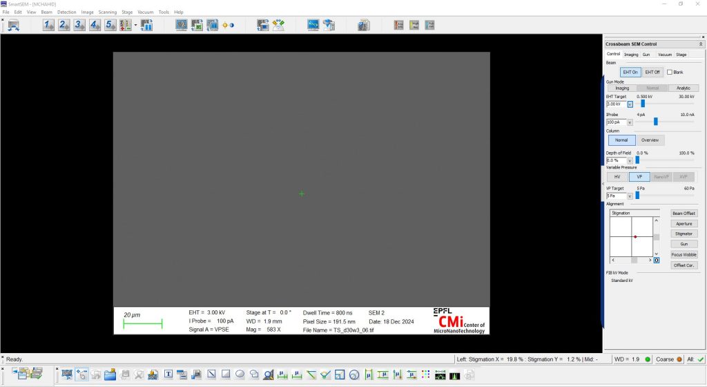
1. In the Crossbeam SEM Control panel, select the Control tab.
2. In the Section Variable Pressure, make sure the VP Target is set to the lowest value, i.e. 5 Pa, if not do it.
4. Then select VP mode by clicking on VP button. The EHT will automatically turn off to avoid any arc during the gaz injection. It will also come back automatically. It is possible to follow the pressure in the chamber through the tab Vacuum.


5. When you selected the VP mode, the system also automatically switched the detector to VPSE one. If not, go the Crossbeam SEM Control panel, select the Imaging tab.
6. From the Signal A drop-down list, select VPSE.
7. In the Crossbeam SEM Control panel, select the Imaging tab.
8. In the Section Collector Voltages, use the Collector Bias scroll bar or double click for Input field and make it to 300V. This tension is a good value to start to find out a signal on the screen.
9. Play with the different following parameters to obtain a good contrast image:
- the energy of the electron beam EHT;
- the current of the electron beam IProbe;
- the Collector Bias;
- the VP target pressure (in the Crossbeam SEM Control panel Control tab).
Some guidelines should be kept in mind during the preliminary training for using VP mode.
10. In the Crossbeam SEM Control panel, select the Control tab.
11. In the Section Variable Pressure, press the HV button and wait the system to come back at nominal high vacuum pressure. Again make sure the VP Target is set to the lowest value, i.e. 5 Pa, if not do it.
12. Unload your sample and Exit the SmartSEM software before to logout from the tool.